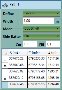
The path element is used to define a path with a fixed width and defined levels. This element is most commonly used for roads and trenches.
The properties that are exposed for this element are summarised below.

|
-
Define
This is the way that the path level should be defined. Options are 'levels' which uses the levels specified in the table below
without modification, 'levels & offset' which applies an offset
to the levels specified. The offset option is mostly used to add construction thicknesses by specifying a negative
offset. Lastly a 'depth' option allows the path levels to be specified in terms of a height or
depth above or below the existing ground. For depths negative values must be specified when using this option.
-
Offset
This option is only visible if offset options are selected in the 'Define' menu. It allows you to offset the entire
path in Z. This is useful for accommodating for a construction thickness.
-
Width
This is the width of the path.
-
Mode
This is used to specify if the element should have cut, fill or both. Most commonly cut and fill will be specified.
-
Side Batter
The path boundary is joined to the ground by side slopes. The side batter (set as a ratio of vertical to horizontal) dictates the angle of these slopes. You can set differet side batter angles for side slopes that cut into
the ground and for those that fill into it. Turning side batter off will result in the path being joined to the ground with vertical sides.
-
Definition Points
These are the points which define the outline as well as the levels (or depths) for the path. If levels & offsets are being
defined, the levels entered into this table will be offset by the value specified.
|
|
The following video tutorials relate to this topic:
[1] Proposed Earthworks : The Path
Element
: A video which demonstrates how to easily produce estimates for linear structures like trenches, roads and causeways.
|
