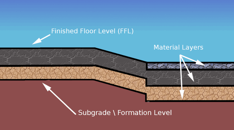
Most site plans do not have the sub grade level marked. Instead they mark the final finished level (FFL) and a separate plan of surface material thickness. When estimating bulk earthworks we need to calculate to the subgrade so we need to find a way of adjusting for the subgrade in our project. There are two different techniques recommended to adjust the FFL levels to the subgrade level : the offset method and the strip method.
Notes on Terminology : In some areas of the world the term 'subgrade' is used and others 'formation level'. There are also a number of different terms used to refer to the the level you will be standing on when the project has finished : 'finished floor level', 'finished grade' and 'final floor level' are all used.

The Offset Method
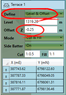
The first method is called the offset method because we use the Z offset value that is available in all explicit level elements to offset an element with a negative value to make the required adjustment to the finished level. The Z offset input box is not available by default and has to be turned on by changing the define drop down in an element's properties for an option that includes an offset.

This offset method works very well when the different areas of material thickness are represented by different elements in a project. For instance if you have four building pads represented by four platforms and a car park represented by a feature surface it is easy to offset each platform and the feature surface to adjust for different material thickness values. However if the car park had different material thickness values across its surface we would run into a problem as there is only one Z offset box for the entire feature surface. We could split it up into different chunks but this can be awkward. Therefore in this scenario the strip method can be used to work around the problem.
The Strip Method
The strip method is frequently used when the proposed is defined by a single set of elevation features (contours, break lines, points). Breaking the proposed into different elements to cover different material thickness areas can be awkward and can lead to undesirable results at the boundaries of the different elements do not join seamlessly if the elevation features were not designed to be broken up like this. In these scenarios it is usually best to use a single feature surface and draw strips over the feature surface to adjust the different areas by the required thickness.
The reason this works is because strip elements are level adjustment elements, this means they can not only adjust the level of the ground but also can be used to adjust the level of elements lower in the calculation order. When using this method we need to make sure the following rules are followed:
- Strips must be in the same phase as the elements that define the finished level.
- The strip elements must be below the finished level elements in the calculation order.
- Usually the strips should have the side batter turned off.
- Strips that intersect have a cumulative effect. It is a good idea to use snapping to make sure adjacent elements do not intersect
|
Video Guides The following video tutorials relate to this topic : [1] Adjusting to Subgrade \ Formation Level: Looks at adjusting the FFL levels to the subgrade level using two different techniques: the offset method and the strip method. |