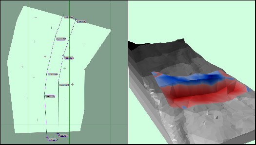
There are broadly two different approaches to defining retaining walls; The first is using break-lines within a feature surface the second involves combining different elements together like the platform and path together. If adjusting to subgrade using the 'reduce method' (i.e a feature surface with a number of reduce elements) then you would use break-lines within the feature surface. If however, you were using the 'offset method' you could still use break-lines within a feature surface, but there is also an option of building up the retaining wall with various elevation elements.
Break-Lines
With the break-line method you would first input the elevations on both sides of the wall. These would likely be points but could also be with contours that stop just shy of the wall. You then would input two break-lines. One at the top of the wall and one at the bottom. The gap between the break-lines would indicate the width of the wall slope when viewed on a plan. For instance, a near vertical wall would have break-lines very close whereas as are gentle slope would be much wider.

Combining Elements
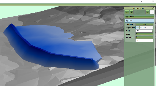
Another approach with retaining walls is to define them by combining different elements. For instance, the wall itself can be represented by a path (using absolute elevations) or a berm (using relative elevations). The backfill can then be defined with a platform element if the area is flat or a slope or feature surface if not. With the backfill element it might be advantages to set the mode to ‘fill only’ so the element only fills to the ground and wall level rather than cuts from it.
