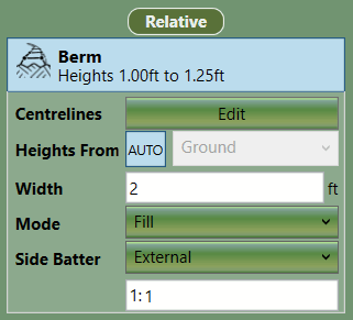
The Berm element is used to define a raised linear path with a fixed width and variable
heights. This element is most commonly used embankments.
The properties that are exposed for this element are summarised below.
|
-
Centrelines
Edit button provides access to the editor wherein the definition points can be
defined for the outline as well as the heights for the Berm.
- Heights From
This setting dictates from what surface the specified heights
are relative to. ‘Ground’ can be selected or you can select the ‘Previous Element’
if you want the heights to be relative to the surface when the previous element in
the calculation order is built. You can also select a named element. When the ‘Auto’
option is active ‘Heights From’ is dynamically set to the first absolute element
above it in the calculation order. If there aren’t any, it is set to ground. The
behaviour when ‘Auto’ is active is desirable in most circumstances.
-
Width
This is the width of the Berm.
-
Mode
This is used to specify if the element should have cut, fill or both. Most commonly cut and fill will be specified.
-
Side Batter
The Berm boundary is joined to the ground by side slopes. The Side Batters (set as a ratio of vertical to horizontal)
dictate the angle of these slopes. You can set different side batter angles for side
slopes that cut into the ground and for those that fill into it. You can set the
side batter to either External or Off. Turning side batter off will result in the
Berm being joined to the ground with vertical sides.
Between the Cut and Fill
is a button which (when depressed) will synchronise Side Batters.
|

|
Estimate linear structures such as trenches, roads
and causeways with the Proposed Earthworks : The Path video. For more complex
roads, consider using a Feature Surface with varying level outlines and a centre
line (defined by a break-line), or contours. |